Banned Book Library in a Wi-Fi Smart Light Bulb
Comments
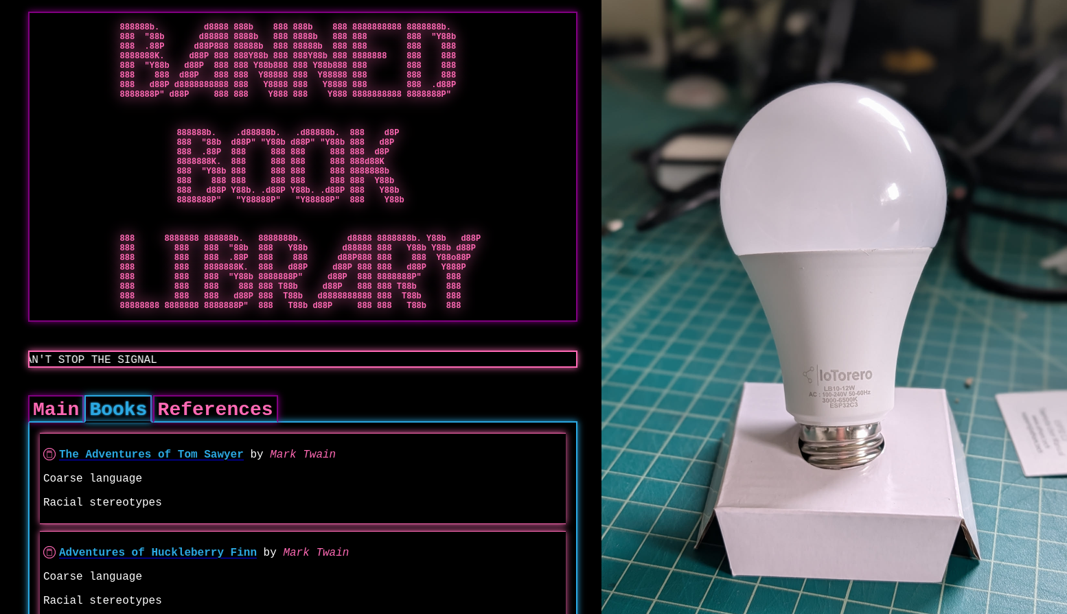
Overview A long while back I had an idea to hack a WiFi smart light bulb to do something more useful to me. Actually, I had a few different ideas of things to do with them. One of these ideas was to modify the device to have an open WiFi access point and a web server hosting banned books. The idea was that if you lived somewhere that banned books you thought were important, you could theoretically stick a digital copy of the book on one of these light bulbs. Then you could go install it somewhere in your community. As long as the light bulb is switched on, then anyone in the vicinity can still access the banned material assuming they have an electronic device with WiFi. Since the device is a light bulb, it would be difficult to detect and likely to go unnoticed. A cyberpunk digital dead drop. These devices are also fairly inexpensive, so leaving them around town as is hopefully not very cost prohibitive. I think the idea hosting banned books specifically came to me after having read Ben Brown's short story Library. It's been a while since I read it, but if I recall there are characters in the story who maintain a "library" which acts as a digital archive of creative works, owners manuals, 3d models, etc. Things that others might find useful or interesting that you wouldn't want to lose should they be somehow wiped from the Internet. That's only a part of the story and it was a fun read. You should go read it! Anyway, a few months ago I decided to finally get to work on this project. The result is the Banned Book Library! Hardware I brought up this idea with some folks at my local DEFCON meetup group. One of them had some experience with home automation and recommended I look into Tasmota. Tasmota is an open-source firmware you can install on various smart devices to integrate them into a home automation system such as HomeAssistant. The main idea with this firmware is to provide you with local control over the device. Many of these devices rely on cloud services that change over time or sometimes completely disappear, leaving the devices unusable. Tasmota allows you to untether yourself from these cloud services and host everything internally. Actually, this is another great parallel to Ben Brown's Library story. Also relevant is Cory Doctorow's Unauthorized Bread. I hadn't heard of Tasmota but after reading about it, it sounded like a good way to go. I had sort of expected many of these smart light bulbs would rely on ESP32 chips, or similar. Having no experience with them made it feel a bit daunting to get started. I thought maybe it might be easier to modify the Tasmota firmware to do what I wanted instead of writing something from scratch. I did not end up modifying Tasmota in the end, but this rabbit hole did lead me to find a website that sells WiFi light bulbs with Tasmota pre-installed. The product page even specified that the bulb uses an ESP32C3 4MB . It also listed which GPIO pins were used to control the various LEDs, which would come in handy later: R:GPIO6 G:GPIO7 B:GPIO5 CW:GPIO3 WW:GPIO4 This seemed like a great starting point because although Tasmota supports many other devices, not all of them can be flashed over the air (OTA). Many of them require breaking them open, soldering on small wires, and flashing via a serial programmer. Tasmota has a built-in mechanism to update the firmware OTA, so it seemed likely I might be able to flash my own modified Tasmota firmware, or otherwise a custom firmware without having to tear the light bulbs apart. The one thing that struck me as a potential problem was the flash size. It was listed as 4MB. This is not very much space to host a library of books... That 4MB would need to fit all of the firmware, the website, and any books. Not much space. I thought I might be able to overcome this by adding storage, such as a microSD card reader. More on that later. I purchased two of these bulbs to play with. I figured I might end up breaking or bricking one, so having a backup would be good. Teardown The bulbs showed up in the main a few days later and I opened up the box to check it out. The first thing I wanted to do was open it up and see what I was working with. I was mainly wondering if the pins were exposed so I might be able to attach a microSD card reader. To remove the white plastic bulb on top, I ran a razer blade around the circumference of the bulb in between the base and the bulb. I had to go around twice, the second time angling the knife downward to cut through the sealant inside. Then I was able to just twist and pull the bulb right off. Minimal damage. This revealed a round daughter board with all of the LEDs on it. This PCB was attached to another one underneath using six pins. There was also a hole in the middle where the mother board stuck through a bit. This ended up being the antenna for the ESP32. The bulb housing was lined with aluminum and the daughter board was also made of aluminum. So they likely designed it this way to ensure a decent wifi signal. The daughter board was glued in with more sealant. I used my knife to cut through this and a small, flat screwdriver to carefully pry the daughter board out. I slid it up so it would separate from the mother board. Now I could very clearly see the ESP32C3 inside, as well as some other supporting circuitry. I'm no electronics expert, but I believe most of the components inside are to convert the AC mains power to a cleaner 3.3V DC for the ESP32 as well as whatever voltage was needed to drive the LEDs. I never plugged this device into mains while it was open so I didn't measure the voltage for the LEDs. One nice thing about this ESP32 was that it seemed to have a bunch of pins exposed. I hoped this might make it possible to solder on a microSD card reader for expanded storage. You can also see some of the pins are labeled at the bottom to let you know which pins are for which colors. There was really no way to get a soldering iron inside the bulb. The ESP32 only had the antenna portion sticking out above the housing. The only way I was going to solder any wires to those pins was to remove the mother board. Unfortunately this was not a simple task. The mother board was held in place with some kind of rubbery potting compound. There was... a lot of it. I had to dig it out with a knife and screwdriver and then yank the board out. I chipped away a bunch of the compound from the mother board to get a better look at it. It made a mess. This was a huge pain and not something I would want to be a required step in the process of setting up one of these dead drops. I really wanted this project to be as accessible as possible, requiring minimal tools and hardware skills. Not only that, but there really was no way I was going to get this re-installed properly. And even if I managed to get it back in, I wouldn't trust it to be safe. It could become a fire hazard for all I know. All that said, this did give me a bit of a development platform to work from. I thought since I had this thing apart anyway, I might as well solder on some wires for serial programming. I had not done this before, so I had to do some reading to figure it out. Basically, I needed to power the chip with 3.3v and ground. Plus I need one wire each for the serial UART TX and RX pins. The first question to answer was which pins were the right pins? I managed to find this exact module on AliExpress. The listing included an image of the backside of the module, which thankfully had labeled all of the pins. This helped me figure out the VCC, GND, TX, and RX pins. For GND I ended up just soldering to the metal shielding as it was also grounded and much easier to solder to. I soldered wires to all of the other pins. I had to remove a few capacitors in order to get in there. In order to program the device via serial, you have to boot it into a special download mode. This seems to normally involve shorting one of the ESP32 pins to ground while it is powered on. I can't remember how I figured this out, but it ended up bing the IO9 pin in this case. So I soldered another wire there. I set my bench top power supply for 3.3v and hooked it up to the chip. Applying power to the VCC and GND wires did boot it up and I could see the IoTorerro access point waiting for me to connect and configure the device. To get it into download mode, I powered the device off. I connected my FTDI device to my laptop's USB port and then to the GND, TX, and RX wires on the mother board. Then I manually shorted the IO9 wire to the shielding to ground it. Then I powered the device on. I could see this time it was only drawing about 0.09 amps, which was much less than before. So something was different. I thought the first thing I should probably do is try to dump the entire firmware. This would hopefully allow me to flash it back to the device to start it back over from a clean state. I used esptool to do this. esptool --chip esp32c3 --port /dev/ttyUSB0 --baud 114200 read-flash 0x0 0x4000000 ./tasmota_original_firmware.bin I could see that it was able to talk to the device and after a few minutes I had a firmware dump! Things were looking good so far. Early Experiments Hello World Early on I went looking at the Tasmota source code to see if I could modify it to act as the Banned Book Library. The firmware was much more complicated than I had anticipated. Not only that but it supported all different architectures and devices. It also had many features I really didn't need. And considering the purpose of my project, I wanted to try and keep the firmware bloat down to make more space for book storage. So I scrapped the idea of modifying Tasmota. I then discovered that you can program ESP32 devices with Arduino. I had used Arduino a bunch maybe 10-15 years ago, so I had some experience with it. I recalled it being pretty accessible and making it easier to work with embedded systems. But I was definitely rusty and I had never used it to program an ESP32 before. I setup the Ardui
Comments
No comments yet. Start the discussion.